Over the weekend I managed to fully build one shoe and solved some wheel placement problems as well as started to add structural support for the x-brace and body.
I was able to test the shoe and the performance was mediocre. It has lots of torque and does go up and down in gear ratios as needed. Going up an incline seems fine and it is slow as expected.
There is a problem however. On flat ground the shoe lurches, slows down, and lurches again. This is at any motor speed. Best I can tell is that it seems to be that the many dive axles that twist and retain a lot of torsional power like a spring that lets loose once the friction on the drive line is reduced. There is an especially long set of connected axles from the transmission to the sprocket of 17 studs.
This is probably exacerbated by the final output shaft having a 1:1 drive ratio with the drive sprocket and incomplete structural bracing.
I'm going to try a 1:2 gear ratio at the drive shaft.
If that fails I'm thinking I have to redesign the cvt to pass power more directly by gears than by axles. I can't see that being possible, but I haven't tried that yet.
Monday, July 31, 2017
Friday, July 28, 2017
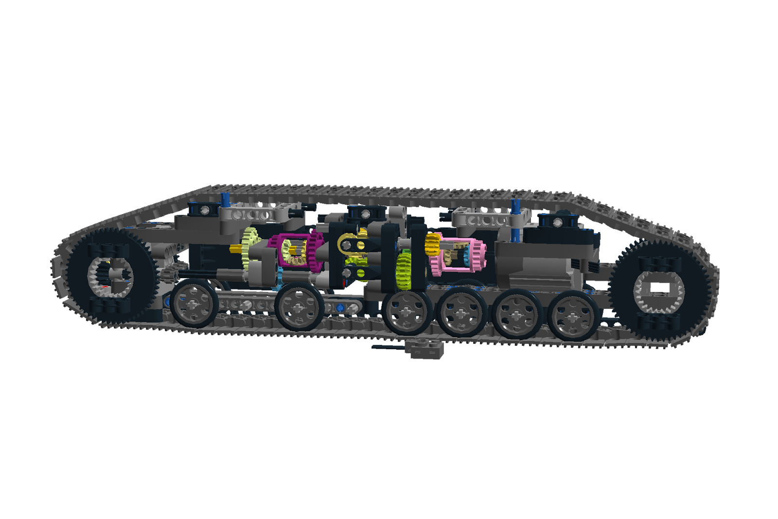
EC750E shoe with cvt, sprocket, and most wheels
After many rebuilds and a poor translation of the cvt design I made to fit in the shoe a design has finally emerged that feels like it works. There are some bracing issue to deal with for the anticipated weight of the whole vehicle.
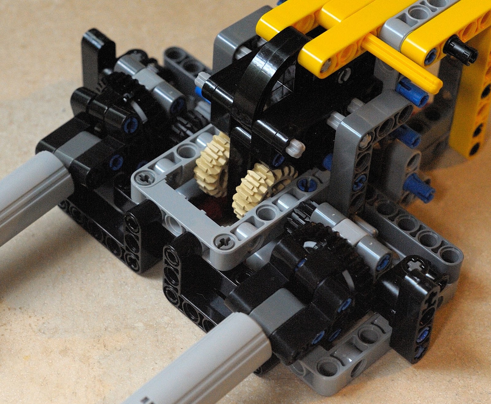
 This is the cvt rebuilt and working nicely with good internal bracing. I left a couple wheels and track pieces for reference to position in the shoe.
 This is the view of the shoe from the center of the digger.
 This is the view as seen from the outside by viewer. The length is 48 studs which is a tad longer than I would like, but close enough.


Wednesday, July 26, 2017
Lego mayhem
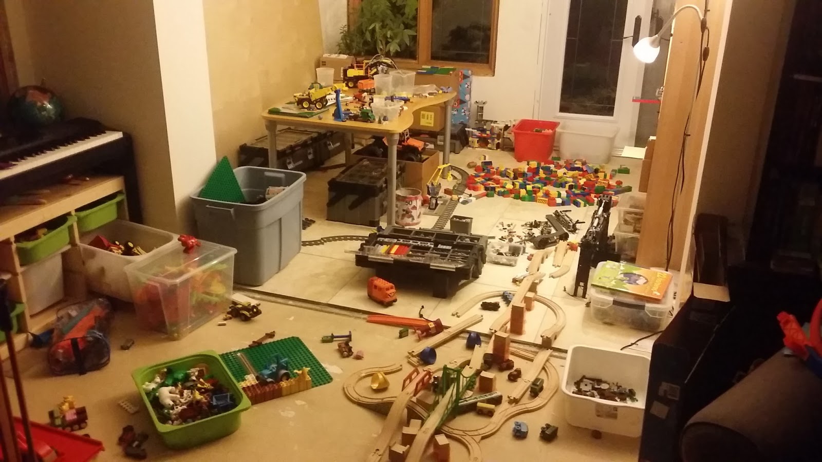
This is where I make my Lego creations:

This mess is located in the back half of my living room and could use some explanation. My three year old did all of this in one day. In the morning we built a wooden train track, in the afternoon he built a Duplo volcano on the big green Duplo base plate visible in the front with the blue Duplo farm tractor on it. In the evening he explained how everything worked and the mess of a colour layout on the volcano including the red lava. He then proceeded to explode the volcano in a matter of minutes and that is how that massive pile of Duplo ended up on the floor at the back. This was to free the baseplate to make a farm the next day. Mostly you see wooden train track, but you'll also note the Lego city train track around the table and the large blue Rubber Maid bin is full of Duplo train track. We like our trains. Shelves of model trains and other MOCs not shown. The IKEA six bin piece of furniture with the piano on top is full of Duplo pieces. Two more big IKEA bins/drawers hold the 2x2 and 2x4 Duplo bricks respectively. The three tool boxes at the back hold sorted Lego. The toolbox under the table and the one open on the floor holds my sorted technic bricks. The cardboard box under the table holds an orange Jeep 4x4 MOC and all the extra technic tires, rims, and currently most of a spare Volvo loader. This room changes how it looks a lot so I work on the floor. That spot in the middle between the Duplo and the open toolbox is where I was sitting before taking this shot. The big black arm thing to the right and on the floor is the arm of the EC750E MOC I'm currently working on. Hard to see, but a pile of CVT gearboxes for testing is what I was working on at the time.
This mess is located in the back half of my living room and could use some explanation. My three year old did all of this in one day. In the morning we built a wooden train track, in the afternoon he built a Duplo volcano on the big green Duplo base plate visible in the front with the blue Duplo farm tractor on it. In the evening he explained how everything worked and the mess of a colour layout on the volcano including the red lava. He then proceeded to explode the volcano in a matter of minutes and that is how that massive pile of Duplo ended up on the floor at the back. This was to free the baseplate to make a farm the next day. Mostly you see wooden train track, but you'll also note the Lego city train track around the table and the large blue Rubber Maid bin is full of Duplo train track. We like our trains. Shelves of model trains and other MOCs not shown. The IKEA six bin piece of furniture with the piano on top is full of Duplo pieces. Two more big IKEA bins/drawers hold the 2x2 and 2x4 Duplo bricks respectively. The three tool boxes at the back hold sorted Lego. The toolbox under the table and the one open on the floor holds my sorted technic bricks. The cardboard box under the table holds an orange Jeep 4x4 MOC and all the extra technic tires, rims, and currently most of a spare Volvo loader. This room changes how it looks a lot so I work on the floor. That spot in the middle between the Duplo and the open toolbox is where I was sitting before taking this shot. The big black arm thing to the right and on the floor is the arm of the EC750E MOC I'm currently working on. Hard to see, but a pile of CVT gearboxes for testing is what I was working on at the time.
Friday, July 21, 2017
EC750E Two speed automatic CVT shoe drive
The Volvo EC750E has an interesting drive system. It has an automatic two speed transmission driving each shoe. A planetary gear set may be a compact way of getting a high gear ratio, but it will not change speed as the terrain gets harder to drive over such as up an incline. Having a two speed automatic helps having low speed and higher speed when on terrain with little resistance. Another option is to use a train controller, but not everyone has a train controller for their PF technic sets to set one of eight speeds per channel. It is also hard to remotely choose the power level that each track needs. Seems to me that a cvt would be the best solution for a gearbox per shoe to drive this model. The benefit being that having an automatic variable transmission between an arbitrary low speed and a high speed enables the excavator to choose for itself the torque that it needs at any given time to get over an obstacle. Hopefully without stalling.
How does a cvt transmission work? Good question. Let's start with what it is at a high level.
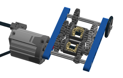
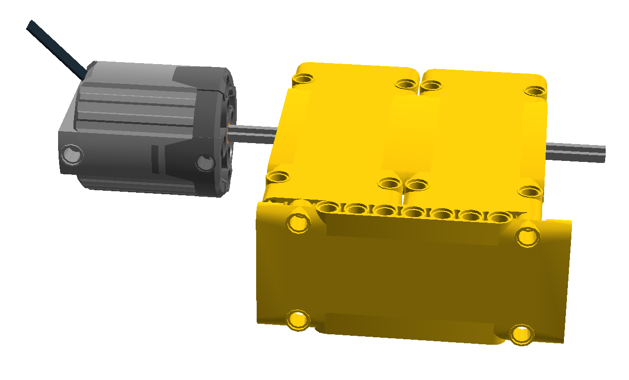
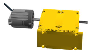 This is a motor going into a box that produces an output drive axle. The input goes in at one rotation speed and the output may be a different output speed in either direction or no speed at all.
If we want to make a CVT we need to look at what the rules are for this box. A CVT is defined by its lowest and highest gear ratios. In other words the output speed will be in the range of the lowest to highest ratios of the input speed. For example let's say a sample CVT has a lowest ratio of 1:4 and a highest ratio of 1:1. This means that a rotation speed of 100rpm produces an output range of 25 to 100 rpm. The speed of the output varies based on the torque required to drive the output shaft or by a manual control(as in a car with CVT). In this case we want the output speed to be automatically chosen based on the resistance encountered.
You may have encountered some flavour of this Lego CVT:
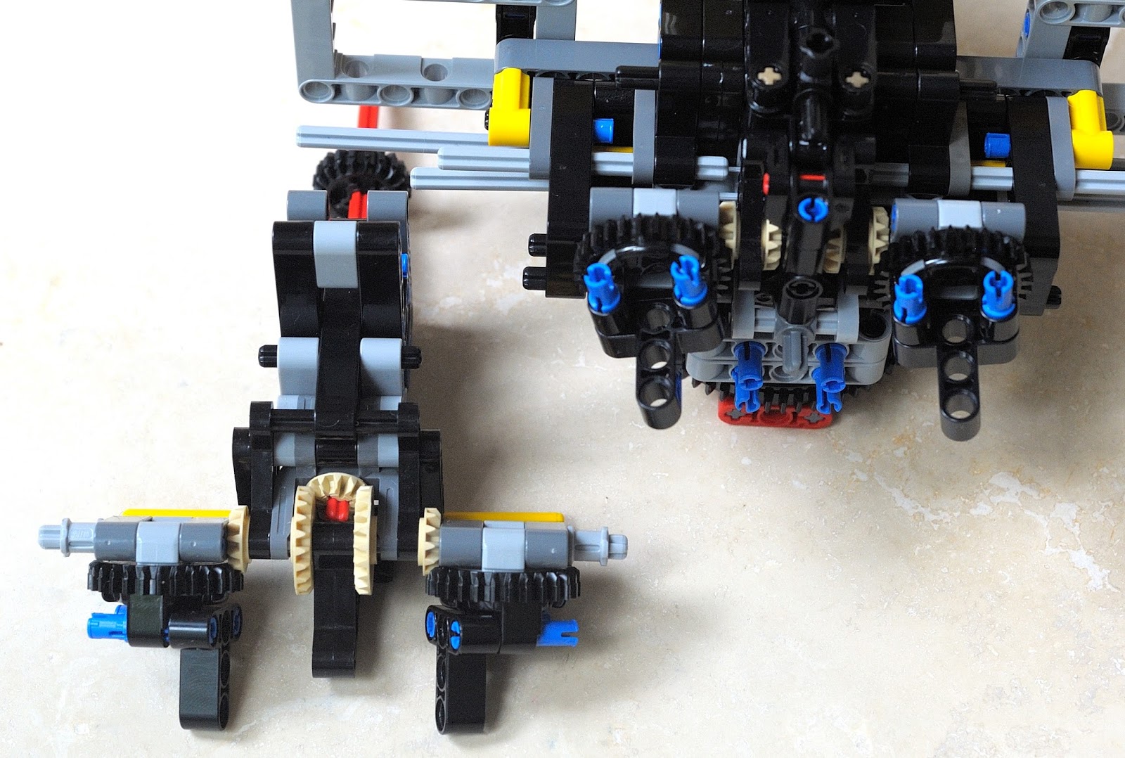
 Let's break down what is happening here. The motor drives a small 8 tooth gear that drives the first open differential. The job of an open differential is to transmit power equally to each output shaft. The tan coloured gears in the middle see to this.
The output on the left of the first open differential is a large 24 tooth gear that drives another 24 tooth gear that finally drives the second open differential. Since both gears are the same size it is a 1:1 ratio on that side.
The output on the right of the first open differential is a small 8 tooth gear that drives a much larger 40 tooth gear which in turn drives the second differential. The ratio in this case is 8:40 or 1:5.
Finally the second open differential combines the two drive shafts into one output by averaging the input speeds (or so we hope). It is important that the differentials are of the open type so that power can be instantly transferred back through the drive shafts.
Imagine that there is no friction on the wheel and the gears can all spin freely. In this case we would have both the high and low ratios in the same amount and at the same time. The second differential would combine the two. In the example of 100rpm this would be an addition of 20 and 100 (120) then divided by 2 equaling 60rpm. If the vehicle were moving down a hill it could get up to 100 rpm at its maximum without overpowering the motor. If it were going up a hill then we would expect the lowest speed to be 20rpm. On a small incline this may happen, but there is a problem in practice. What happens when the driven wheel is locked and cannot spin? For the implementation above it is that the net output power is zero. Why is that? Shouldn't it be 20?
This implementation permits all gears to spin in any direction freely so if the output shaft is at zero speed then the power has to go to the other shaft. Since neither shaft entering the second differential have any rotational bias, both shafts fight one another until the one with the least resistance loses and is rotated backwards. Once this happens all power to the ouput shaft is gone except for the amount required to overcome the minimal resistance in the entire system. One solution is to put fly-wheels on the two shafts so that they maintain momentum, but this is not a fix as it still only woks while the output shaft can rotate.
For my purposes this is not sufficient. I can't have the output power become zero if the driven wheel is stalled. In this case I need even more torque with a guaranteed minimum output speed just like a pneumatic drive has a guaranteed amount of output power even at stall.
If we could limit the stall behavior to not permit the counter-rotation then we would have better results. If we use some form of friction wheel or even a limited slip differential there would still be some upper bound that would overcome the internal friction. If we dictated that the gear reduced drive shafts were driven in only one direction we would still have the benefit of the open differentials, but in slightly more limited output.
Looking at the stall case we want power out to equal the lowest ratio side. In other words the output needs to be low gear ratio rotation speed minus no input from the high ratio side. If the lowest gear ratio side wire limited to only rotate in the direction driven then the driven wheel would be guaranteed this lowest rotation speed in the case where it were attempted to be stalled. This does mean that if the motor can overpower a gear or axle in the transmission that something will skip or worse, break. I'm willing to take that chance, but for those not, just add as many clutch gears in parallel as desired on the output of the motor (the Lego BWE uses two on its XL motor).
 Here is the same transmission with the low gearing converted to a one-direction low gearing.
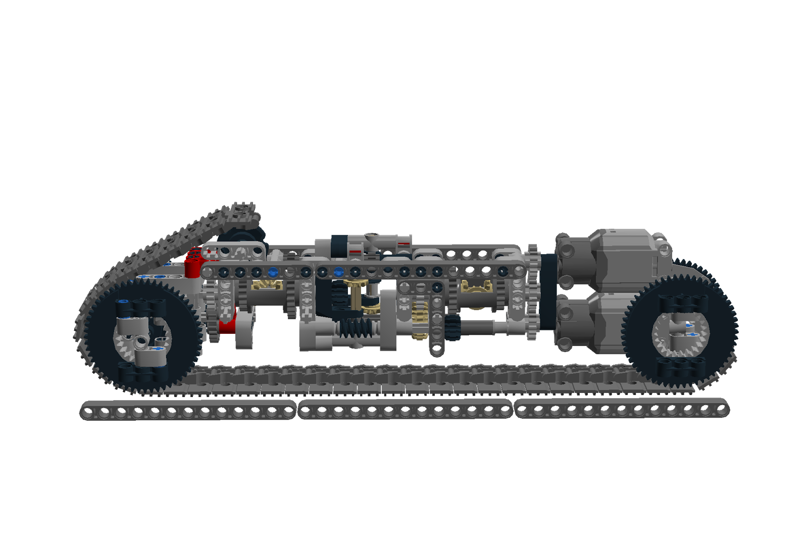
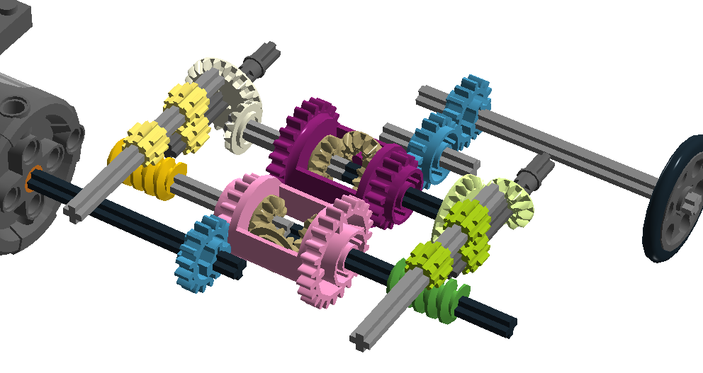
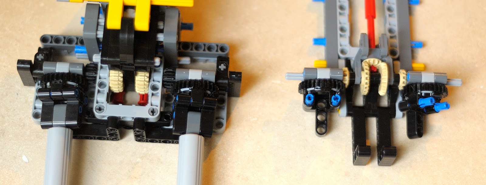
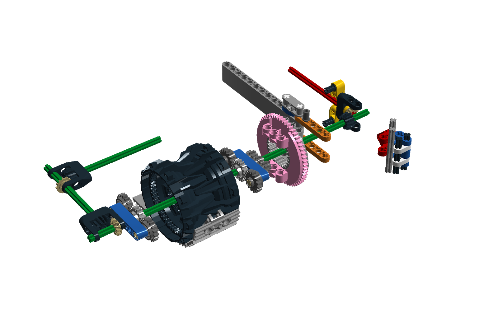
Here it is again with both gearing sides converted, support structures removed and coloured for easier viewing.

Power from the motor turns the 16 tooth gear that drives the pink differential that drives a grey shaft and a black shaft. The grey shaft drives the yellow gear set for roughly a 1:5 ratio. The black shaft drives the green gear set for a ratio of 1:13. The two gear sets recombine in the purple differential and outputs to the blue 16 tooth gears.The output power equals the motor's output power at all times though the speed varies within the given ratios. In practice the whole system has a problem with using the low gear side even if the motor could drive the high side exclusively because the low side is easier to drive. A simple solution to this is to add a small rotational resistance to the low ratio gearset(green) before it enters the purple differential. The resistance needs to be equal to the gear resistance of running the high side(yellow gears) so that the green side is not used unless it is truly needed because the motor can not drive the high side.
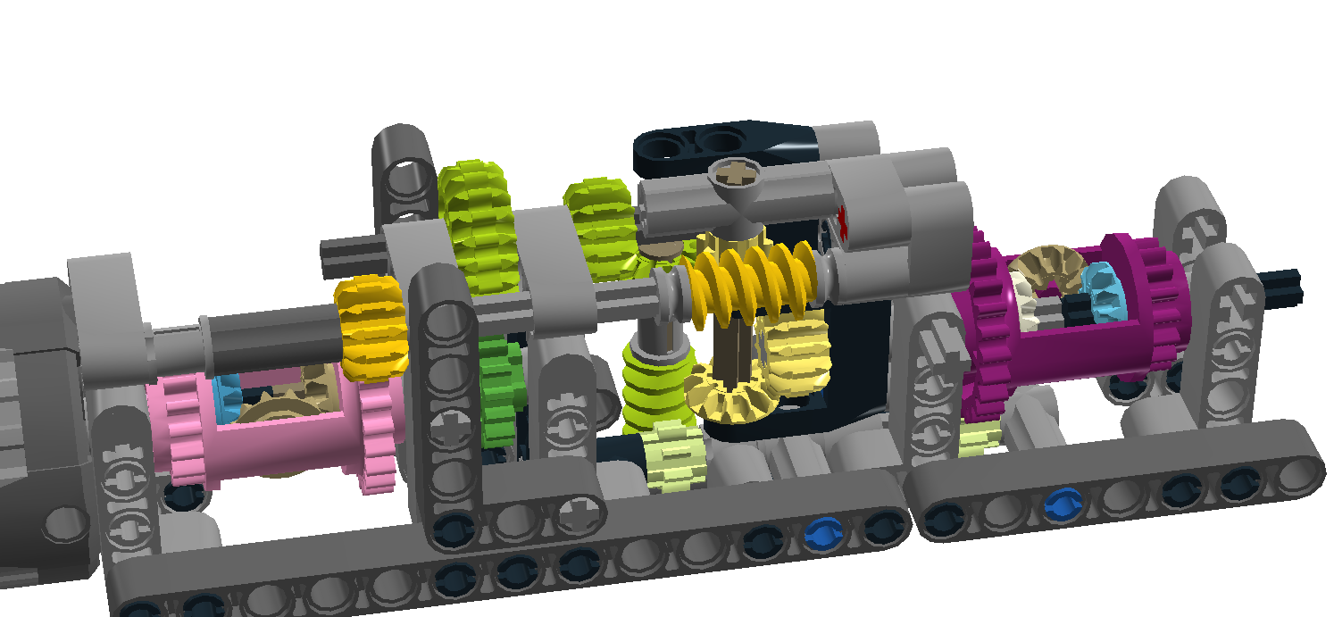
I have built several gear boxes to test this and it does work as desired, but doesn't look like it will fit in an excavator shoe. The next challenge is reshaping it to fit within the dimensions of the MOC's shoe: mostly 5 studs wide, 8 studs tall for the frame not including rollers/sprockets. This means that no gears should protrude from these dimensions at all.

This is getting closer. Now I still have to figure out what I'm going to do about the sprocket.
How does a cvt transmission work? Good question. Let's start with what it is at a high level.
If we want to make a CVT we need to look at what the rules are for this box. A CVT is defined by its lowest and highest gear ratios. In other words the output speed will be in the range of the lowest to highest ratios of the input speed. For example let's say a sample CVT has a lowest ratio of 1:4 and a highest ratio of 1:1. This means that a rotation speed of 100rpm produces an output range of 25 to 100 rpm. The speed of the output varies based on the torque required to drive the output shaft or by a manual control(as in a car with CVT). In this case we want the output speed to be automatically chosen based on the resistance encountered.
You may have encountered some flavour of this Lego CVT:

The output on the left of the first open differential is a large 24 tooth gear that drives another 24 tooth gear that finally drives the second open differential. Since both gears are the same size it is a 1:1 ratio on that side.
The output on the right of the first open differential is a small 8 tooth gear that drives a much larger 40 tooth gear which in turn drives the second differential. The ratio in this case is 8:40 or 1:5.
Finally the second open differential combines the two drive shafts into one output by averaging the input speeds (or so we hope). It is important that the differentials are of the open type so that power can be instantly transferred back through the drive shafts.
Imagine that there is no friction on the wheel and the gears can all spin freely. In this case we would have both the high and low ratios in the same amount and at the same time. The second differential would combine the two. In the example of 100rpm this would be an addition of 20 and 100 (120) then divided by 2 equaling 60rpm. If the vehicle were moving down a hill it could get up to 100 rpm at its maximum without overpowering the motor. If it were going up a hill then we would expect the lowest speed to be 20rpm. On a small incline this may happen, but there is a problem in practice. What happens when the driven wheel is locked and cannot spin? For the implementation above it is that the net output power is zero. Why is that? Shouldn't it be 20?
This implementation permits all gears to spin in any direction freely so if the output shaft is at zero speed then the power has to go to the other shaft. Since neither shaft entering the second differential have any rotational bias, both shafts fight one another until the one with the least resistance loses and is rotated backwards. Once this happens all power to the ouput shaft is gone except for the amount required to overcome the minimal resistance in the entire system. One solution is to put fly-wheels on the two shafts so that they maintain momentum, but this is not a fix as it still only woks while the output shaft can rotate.
For my purposes this is not sufficient. I can't have the output power become zero if the driven wheel is stalled. In this case I need even more torque with a guaranteed minimum output speed just like a pneumatic drive has a guaranteed amount of output power even at stall.
If we could limit the stall behavior to not permit the counter-rotation then we would have better results. If we use some form of friction wheel or even a limited slip differential there would still be some upper bound that would overcome the internal friction. If we dictated that the gear reduced drive shafts were driven in only one direction we would still have the benefit of the open differentials, but in slightly more limited output.
Looking at the stall case we want power out to equal the lowest ratio side. In other words the output needs to be low gear ratio rotation speed minus no input from the high ratio side. If the lowest gear ratio side wire limited to only rotate in the direction driven then the driven wheel would be guaranteed this lowest rotation speed in the case where it were attempted to be stalled. This does mean that if the motor can overpower a gear or axle in the transmission that something will skip or worse, break. I'm willing to take that chance, but for those not, just add as many clutch gears in parallel as desired on the output of the motor (the Lego BWE uses two on its XL motor).

Here it is again with both gearing sides converted, support structures removed and coloured for easier viewing.
Power from the motor turns the 16 tooth gear that drives the pink differential that drives a grey shaft and a black shaft. The grey shaft drives the yellow gear set for roughly a 1:5 ratio. The black shaft drives the green gear set for a ratio of 1:13. The two gear sets recombine in the purple differential and outputs to the blue 16 tooth gears.The output power equals the motor's output power at all times though the speed varies within the given ratios. In practice the whole system has a problem with using the low gear side even if the motor could drive the high side exclusively because the low side is easier to drive. A simple solution to this is to add a small rotational resistance to the low ratio gearset(green) before it enters the purple differential. The resistance needs to be equal to the gear resistance of running the high side(yellow gears) so that the green side is not used unless it is truly needed because the motor can not drive the high side.
I have built several gear boxes to test this and it does work as desired, but doesn't look like it will fit in an excavator shoe. The next challenge is reshaping it to fit within the dimensions of the MOC's shoe: mostly 5 studs wide, 8 studs tall for the frame not including rollers/sprockets. This means that no gears should protrude from these dimensions at all.
This is getting closer. Now I still have to figure out what I'm going to do about the sprocket.
Thursday, July 20, 2017
EC750E brain dump
I'm still waiting for parts, but some have come in. The double rims with studs as a sprocket does fit well in size, but does not drive the track at all. I'll either have to use spur gears elsewhere to drive the track or use something else for a spur gear.
While I've been waiting for parts for the shoes I thought about tackling some of the other problems.
One of them is the drive system. The Volvo EC750E has a two speed automatic gearbox per shoe. This permits both high and low speed. It would be nice to have this in the model so what are the parts required. Two motive sources(maybe XL motors), two transmissions(one per shoe), one battery box, one receiver. Due to the rotation of the body I'm expecting to need to locate all of the parts below the body such as in the X-frame and shoes. I find the automatic transmissions done in Lego to be a bit clunky, but they work. I've also looked into Lego CVT transmissions, but they have a big problem in that if rotation is entirely stopped on the output shaft the internal gears battle amongst each other to counter-rotate and torque to the output shaft is lost. This will not do. I'll have to revisit the CVT concept as I would love to have a smooth final drive ratio like say 1:20 to 1:4 depending on the friction of the environment driven on.
The large technic turntable is roughly 7 studs wide, but I need something closer to 11 or 12 studs wide for the model. I've been playing around with all sorts of ideas about how to accomplish this like support rollers front and back, but none have stood up to tests very well. I'm not leaning towards a hybrid technic/system brick solution wherein the force on the turntable will be distributed across a 12L brick built ring and an internal turntable. First try at this resulted in parts pulling themselves apart because of an inability to anchor the weight of the body to the X frame. What I've come to as a solution in to have two stacked central large turntables so that the one on the bottom can pull up on the X frame from underneath and the one on top can push down while sharing the load with the brick built 12L ring that acts like a fixed washer/bearing. There is enough space to have an 8 tooth spur gear driving a type 2 large turntable on top. A type 3 turntable can be used on the bottom for added rigidity over the type 2.
Then there is the problem of the boom drive and possibly the cylinders tearing themselves apart under too high a load. Just for fun I put a 3 pound jar (roughly 1.3Kg) on the front boom of my BWE standard model and supported the central frame with one hand while operating the gear to actuate the cylinders with the other. They held on just fine so I'll move ahead with my own paired design cautiously and do another weight test after the current body revision is built.
Lots more learning about the model and possible Lego implementation has been going on, but I'm a bit stalled while trying to solve too many problems at the same time. Maybe I'll tackle the CVT first.
Thursday, July 13, 2017
EC750E boom drive part 3
Fitting the new narrower cylinder drive still has overlap problems. At 12 stud width it is still too wide to fit in the maximum width that the model can handle before being way out of spec.
Looking at this photo it is clear to see how the turntable overlaps the space for the cab.
 Time to rebuild the boom drive yet again using the half width gears,
giving up a little on final
drive ratio, and using an even thinner support frame to try and achieve a 9 stud
width so that it fits within the space that the model requires on the
frame.
Time to rebuild the boom drive yet again using the half width gears,
giving up a little on final
drive ratio, and using an even thinner support frame to try and achieve a 9 stud
width so that it fits within the space that the model requires on the
frame.

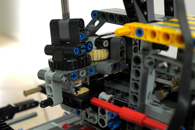
In the photo above the new build is on the right side. It is one full stud width narrower. Note the single half beam between the tan coloured 12 tooth gears. This is the same gearing principles as the prior builds, but lower gear ratio to permit a tighter transfer box. This worked out better for framing strength. Bracing is added in the middle of the gears to always have a support on each side of the gears even in the middle of the transfer box. The space for the boom is now 6 studs, not the 7 that I had originally built so the boom will require a redesign. I may also reconsider the support structure for this boom drive as it would work better structurally if it more closely mimicked the real Volvo body frame:

Looking at this photo it is clear to see how the turntable overlaps the space for the cab.

In the photo above the new build is on the right side. It is one full stud width narrower. Note the single half beam between the tan coloured 12 tooth gears. This is the same gearing principles as the prior builds, but lower gear ratio to permit a tighter transfer box. This worked out better for framing strength. Bracing is added in the middle of the gears to always have a support on each side of the gears even in the middle of the transfer box. The space for the boom is now 6 studs, not the 7 that I had originally built so the boom will require a redesign. I may also reconsider the support structure for this boom drive as it would work better structurally if it more closely mimicked the real Volvo body frame:

Wednesday, July 12, 2017
EC750E boom drive part 2
I created a very basic frame for sizing the width and length of the excavator body based on the calculated Lego dimensions. Comparing the frame to the current boom drive the current
width of 13 studs is clearly not going to work. 27(26.3 rounded up) studs is the
max width of the cab so ideally the cylinders are 9 to 11 studs wide.
Here is the same drive principle, but only 11 studs wide.


Looks good, but there is a problem here. The base of the cylinders is the small turntable and the gear teeth stick out of the 3x3 space into a 4x4 space making the 11 width design take 12 stud width space at best and 13 stud width if counting full width beams. Now we need an even more narrow design, but will it be possible to drive the turntables without resorting to twisty axles?
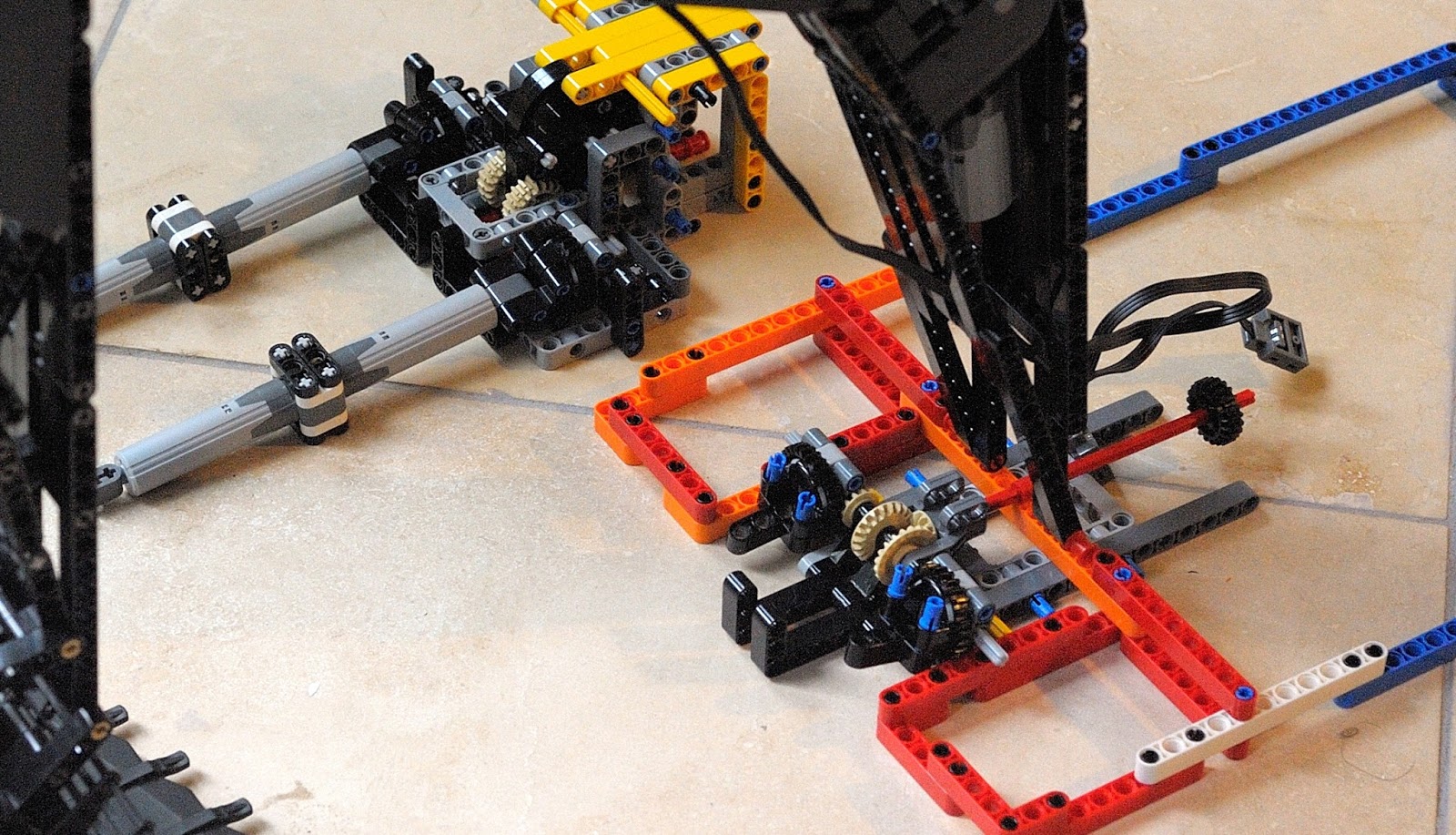
Looks good, but there is a problem here. The base of the cylinders is the small turntable and the gear teeth stick out of the 3x3 space into a 4x4 space making the 11 width design take 12 stud width space at best and 13 stud width if counting full width beams. Now we need an even more narrow design, but will it be possible to drive the turntables without resorting to twisty axles?
Tuesday, July 11, 2017
EC750E boom drive cylinder
Driving the cylinders that lift the main boom requires taking many parameters into consideration. The bucket, arm(3.55), and boom(7.7) fully extended have a reach of 92 studs. If the longest arm were used it would be 100 studs. The pivot point used by the cylinder is 6 studs away from the base of the boom. The cylinder is clearly at a mechanical disadvantage. If the pivot were at 46 studs then the weight of the bucket/arm/boom would be the only force down on the cylinder, but it is at 6. This is a mechanical disadvantage of 7.666. Given that the bucket/arm/boom may weigh up to 1Kg fully laden, the cylinders have a lot of compression force to deal with. Any give in the design of the cylinder drive is going to show quickly.
 This joint fails because the 13L dark grey liftarms that sandwich the light grey 3L cross block used for the drive shaft gears is not locked in place. As the torque goes up the beams pull apart and the whole mechanism fails.
The chassis needs to be able to handle the weight down and the gear boxing needs to arrest the dimensional forces of each gear. More on the chassis later. Two gears in the same plane acting on one another will try to push the other away in the one plane. When two gears are in perpendicular planes the forces push the gears apart in all three dimensions. The simplest way to handle perpendicular gears is to use a box on each perpendicular connection. Having more that one perpendicular connection on a single gear can be tricky as two boxes need to interact together adding to the forces that are trying to pull them apart. Ideally the two perpendicular gear connections are split into two gear sets connected by a driveshaft. This permits more room for structural components even if complexity goes up a bit.
 This setup does the above.

The chassis needs to be able to handle the weight down and the gear boxing needs to arrest the dimensional forces of each gear. More on the chassis later. Two gears in the same plane acting on one another will try to push the other away in the one plane. When two gears are in perpendicular planes the forces push the gears apart in all three dimensions. The simplest way to handle perpendicular gears is to use a box on each perpendicular connection. Having more that one perpendicular connection on a single gear can be tricky as two boxes need to interact together adding to the forces that are trying to pull them apart. Ideally the two perpendicular gear connections are split into two gear sets connected by a driveshaft. This permits more room for structural components even if complexity goes up a bit.
Monday, July 10, 2017
EC750E shoe free spinning wheel
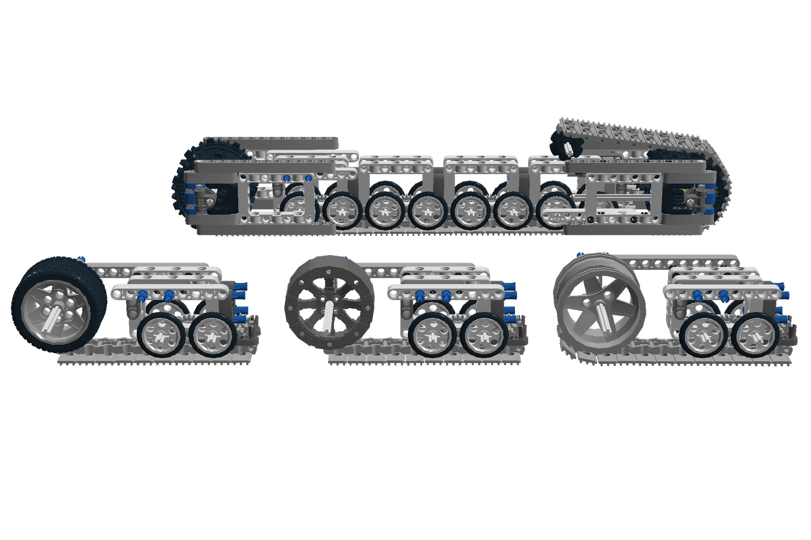
A different track related question is which wheel looks better for the front free spinning wheel/sprocket?
I'm inclining towards the wheel in the middle as it is 3 studs wide whereas the tire is 4 and the wheel on the right is 5.

I'm inclining towards the wheel in the middle as it is 3 studs wide whereas the tire is 4 and the wheel on the right is 5.
EC750E track drive update
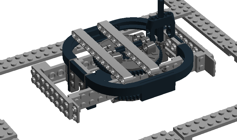
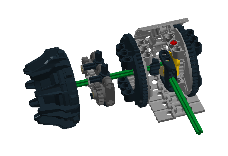
The first track drive design had some problems. Notably the carrier for the planetary gear set was locked to the ring gear instead of the sun gear. Even better would be if it could counter rotate at a fixed rate to increase the output gear ratio. This is done below. The "drive sprocket" is now a paired ring wheel which also solves the problem of how to take power off the drive wheel to drive a proper sprocket since the drive wheel is not a proper sprocket.
 In the picture above, the pink half of a turntable will be removed to permit a more narrow build. Power comes in from the red axle. The blue carriage on the turntable side will spin based on the planetary gear set of the turntable. This will increase the final drive ratio of the ring wheel driving the track by counter rotating the carriage of the drive wheel gear set. Finally the paired drive wheel will continue to transfer power along the green drive axle and power a sprocket somewhere along the track. At least I hope so. Once the parts that I have ordered through bricklink come in, I'll make this for real and test it out.
Thursday, July 6, 2017
EC750E track drive sprocket
The dimensions in studs for each shoe of the excavator is 46 studs long by 8.3(maybe 8 or 9) studs wide by 10.5 studs tall. That means the total shoe structure should be 45 studs long and 10 studs tall with the track making up the remaining space above, below, front, and back.
From the discussion on the Eurobricks forum, there is interest in what sprockets will be used. I have not been able to find dimensions on the diameter of the main drive and idler sprockets at the front and back of the tracks. From various diagrams and photos I'm guessing these to be about 8 studs. The stock sprockets are roughly 3 and 5 studs in diameter; clearly too small. I'm currently considering the wheel from the old mining vehicle for its ability to be used as a planetary gear set and the large turntable for its almost 8 stud size. Probably something like this:
The only problem here is that while the teeth on the type 3 large turntable work on the track because of the larger spacing between teeth(vs type 2 pictured which doesn't), it doesn't drive the track acceptably well when I try it in practice. Probably the driven turntable will in turn drive some other gear mechanism going to a small 3 stud sprocket to drive the track at the same rate. At least that is what I'm hoping since I like the size of the large turntable.
Thursday, June 29, 2017
EC750E Cylinder, linear actuators, pistons, etc...
The small cylinder problem. Lego linear actuators are 11 studs long, has an actuation length of 5 studs and a width of 2 studs. From the dimensions page for the EC750E the linear actuator (aka. cylinder) should be 19.5 studs long and 3 studs wide. This is clearly a grossly undersized cylinder. What if we could fuse two of them together. Would they still work? If connected plunger end to plunger end the new cylinder would be 22 studs long with a 10 stud actuation length. Unfortunately this does not work because the first cylinder can not spin around to activate the second cylinder. A simple solution to that is to let the driven end of the first cylinder to spin freely so that it can drive the second cylinder. This does work, but having the first cylinder not pull out from the driving axle becomes a problem if the cylinders are pulled out of instead of pushed into the axle. Another way to connect them is driven end to driven end. This leaves no shaft to drive, but this can be solved as whichever end will be driven simply has to be able to spin freely. There is another benefit to this arrangement, overall length is now 20 studs as one stud from each cylinder's driven end overlaps the other:
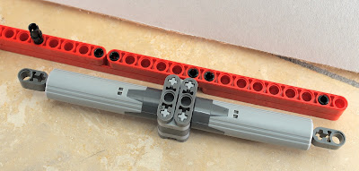
The overall extended length is 30 studs giving a better extended to retracted length ratio than the original cylinder.

Now the problem to solve is how to go about mounting this. The end that we choose to be the "plunger" end can be connected with a pin or axle as normal, but the "driven" end needs some way to be driven to spin around and handle both pull and push pressure just as the single cylinder's original mounting bracket. Thankfully Lego has a turntable that is just the right size for this.
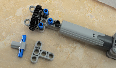
The cylinder's driven end can be mounted to the geared portion of the turntable so as to be driven by gears or alternately the pictured grey axle connector with the 3L pin can be inserted so that it may be driven by an axle.

Lastly one could do both. That is have an axle and gear drive at the same time. For example one may need to drive a second cylinder from one axle source. Red axle powered by an XL motor drives a cylinder through an axle and the gear at the base of the cylinder drives the cylinder on the other side that lifts the boom.
This joint seems like it should work, but the small gears keep skipping because of the high stress of directly driving two cylinders under high load so this will have to be done in some other way.
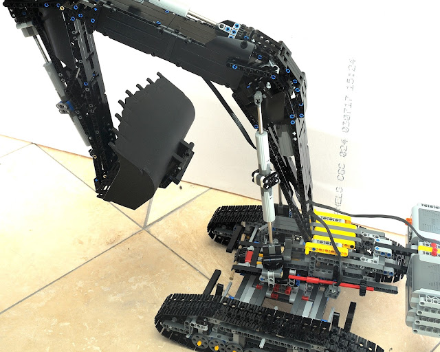
Here is the overall view of how these double cylinders are used to mechanize the model's boom, arm, and bucket.

The overall extended length is 30 studs giving a better extended to retracted length ratio than the original cylinder.

Now the problem to solve is how to go about mounting this. The end that we choose to be the "plunger" end can be connected with a pin or axle as normal, but the "driven" end needs some way to be driven to spin around and handle both pull and push pressure just as the single cylinder's original mounting bracket. Thankfully Lego has a turntable that is just the right size for this.

The cylinder's driven end can be mounted to the geared portion of the turntable so as to be driven by gears or alternately the pictured grey axle connector with the 3L pin can be inserted so that it may be driven by an axle.

Lastly one could do both. That is have an axle and gear drive at the same time. For example one may need to drive a second cylinder from one axle source. Red axle powered by an XL motor drives a cylinder through an axle and the gear at the base of the cylinder drives the cylinder on the other side that lifts the boom.

This joint seems like it should work, but the small gears keep skipping because of the high stress of directly driving two cylinders under high load so this will have to be done in some other way.
Here is the overall view of how these double cylinders are used to mechanize the model's boom, arm, and bucket.

EC750E dimensions
Scale can be a tricky thing when modeling with Lego. We are beholden to the stud width and size of stock parts such as linear actuators. I initially chose a scale of 1 stud = 6 inches as it made for an easy mental conversion of all the dimensions in the Volvo brochure, but this has not worked so well for the arm thickness where it is supposed to be 2'6" (5 studs) over its entire length. This was not possible because bracing and structure have the arm width sticking out to 7 studs. This could have been because I tried to build the shortest arm and a longer one would have had more room to maneuver. The other problem with the scale was that the single cylinder(lineal actuator) or the arm for the bucket had a very short travel and while I got it to perform the necessary 180 degree bucket rotation it wasn't especially strong. The scale was based on the 2'6" grouser fitting nicely with the 5 stud Lego grouser. If we continue to use the grouser for determining scale, the smaller 26" grouser increases the scale slightly to 5.2" per stud. The scaling multiplication factor is now 2.3077. This makes the new arm width of 5.77 studs (6 is close enough). Bracing and structure could be changed to use some thin liftarms to bring the width down to 6 studs. At this point the scaling factor is no longer as easy to calculate. Using the metric measurements it is simple to take the real measurement given and divide by 130 to get the dimension in studs(s).
Below are the Volvo dimensions in studs using the 1:26 scale.


| Overall dimensions | |
|---|---|
| A Width of superstructure | 26.3 |
| B Width of upper structure | 33 |
| C Height of cab | 27 |
| D Tail swing radius | 32 |
| E Height of diffuser | 29.5 |
| Height of guard rail | 31 |
| Height of engine hood | 27 |
| Height of rain cap | 29 |
| Height of cyclone | 29.5 |
| Height of oil bath | 31.5 |
| F Counterweight clearance | 11.5 |
| G Tumbler length | 36.5 |
| H Track length | 46 |
| I Track gauge | 26.5 |
| J Shoe width(650mm) | 5 |
| K Min. ground clearance | 6.6 |
| Overall dimensions | ||||
|---|---|---|---|---|
| Boom | 6.6m (50s) | 7.7m (59s) | ||
| Arm | 2.9m (22s) | 2.9m (22s) | 3.55m (27s) | 4.2m (32s) |
| L Overall length | 94 | 102.5 | 101.5 | 101 |
| M Height of folded boom | 37.3 | 35.5 | 35.5 | 38 |
| Boom | 6.6m (50s) | 7.7m (59s) |
|---|---|---|
| Length | 53.5 | 62 |
| Height | 19.5 | 17 |
| Width | 8.5 | 8.5 |
| Arm | 2.9m (22s) | 3.55m (27s) | 4.2m (32s) |
|---|---|---|---|
| Length | 33 | 38 | 43 |
| Height | 11 | 11 | 10.5 |
| Width | 6 | 6 | 6 |
| Cylinder | ||
|---|---|---|
| Length | Height | Width |
| 19.5 | 4 | 3 |
| Counterweight | |||
|---|---|---|---|
| Length | Height | Width | Weight |
| 26.3 | 13.5 | 5 | 12100kg (scaled to 93kg ??? that can't be right) |
| Shoes 650mm (5s) | |||
|---|---|---|---|
| Length | Height | Overall Width | Weight |
| 46 | 10.5 | 8.3 | 10600kg (?g) |
| Cab | ||||
|---|---|---|---|---|
| Length | Height of cab | Height of diffuser | Width | Weight |
| 42.7 | 20.5 | 23 | 26.5 | 23150kg (scaled to ??g) |
| height of rain cap | 22.5 | |||
| height of cyclone | 23 | |||
| height of oil bath | 25 |
| Cab with shoes (650mm/5s width) | ||
|---|---|---|
| Length | Height of diffuser | Weight |
| 52 | 29.5 | 44350kg (?g) |
| Cab with shoes (650mm/5s width) and boom | |||
|---|---|---|---|
| Boom | Length | Height of diffuser | Weight |
| 6.6m (50s) | 78.5 | 29.5 | 53090kg (?g) |
| 7.7m (59s) | 87.3 | 29.5 | 53480kg (?g) |

| Boom | 6.6m (50s) | 7.7m (59s) | ||
|---|---|---|---|---|
| Arm | 2.9m (22s) | 2.9m (22s) | 3.55m (27s) | 4.2m (32s) |
| A Max digging reach | 88 | 97 | 101 | 106 |
| B Max digging reach on ground | 86 | 94.5 | 99 | 106 |
| C Max digging depth | 55.5 | 59.5 | 64.5 | 69.5 |
| D Max digging depth l 2.4m(19s)/8' level | 54.5 | 58 | 63.5 | 68.5 |
| E Max vertical wall depth | 43.5 | 52 | 57 | 61.5 |
| F Max cutting height | 84 | 95.5 | 97 | 99 |
| G Max dumping height | 54 | 65 | 66.5 | 69 |
| H Min front swing radius | 39.5 | 42 | 41.5 | 42 |
Wednesday, June 28, 2017
EC750E proof of concept
The Lego set 42030 Volvo L350F is one of my favorite sets. So much so that I bought a second set to facilitate the creation of a Volvo A40E dump truck to accompany it. This leaves a large bucket lying around begging to have something made with it.

In comes the idea that maybe suck a large earth moving bucket could be used in an excavator such as the Volvo EC750E.

The first check is the bucket size. The L350F bucket is a spade nose rock bucket with teeth and segments. In real life this bucket is 13 feet wide and holds about 9 to 10 cubic yards. The EC750E's largest bucket is a general purpose earth moving bucket with a capacity of 9.34 cubic yards. It's width is unspecified, and while it will not be a spade nose bucket, the volume is close enough that maybe this could work.
Next is checking to see if and/or how it can be fitted to be used as an excavator bucket since it has the mounting points of a loading bucket. At the same time it would be good to see if the standard Lego linear actuator has enough length to it to rotate the bucket 180 degrees around a pivot. While I was at it I decided to start with a scale of 1 stud = 6 inches (roughly 1:30 scale). This makes the arm 28 studs long(9'6" arm) and the boom 53 studs long(25'3" boom).

Here is the initial proof of concept boom and arm plus bucket:
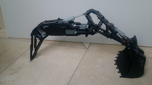
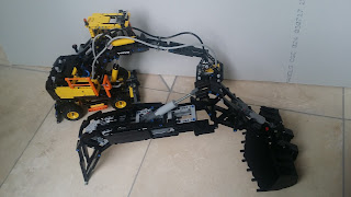
Here it is in comparison to the Lego set 42053 Volvo EW160E:
Since this seems to be feasible I'll continue the build. There will certainly be many problems to be solved along the way.

In comes the idea that maybe suck a large earth moving bucket could be used in an excavator such as the Volvo EC750E.

The first check is the bucket size. The L350F bucket is a spade nose rock bucket with teeth and segments. In real life this bucket is 13 feet wide and holds about 9 to 10 cubic yards. The EC750E's largest bucket is a general purpose earth moving bucket with a capacity of 9.34 cubic yards. It's width is unspecified, and while it will not be a spade nose bucket, the volume is close enough that maybe this could work.
Next is checking to see if and/or how it can be fitted to be used as an excavator bucket since it has the mounting points of a loading bucket. At the same time it would be good to see if the standard Lego linear actuator has enough length to it to rotate the bucket 180 degrees around a pivot. While I was at it I decided to start with a scale of 1 stud = 6 inches (roughly 1:30 scale). This makes the arm 28 studs long(9'6" arm) and the boom 53 studs long(25'3" boom).

Here is the initial proof of concept boom and arm plus bucket:

Here it is in comparison to the Lego set 42053 Volvo EW160E:

Since this seems to be feasible I'll continue the build. There will certainly be many problems to be solved along the way.
Subscribe to:
Posts (Atom)